For about a year now I have been learning about Arduino programming and electronics. I attended a beginners course at www.blekingeuppfinnare.se and I have envolved since. I have learned to program in Arduino modified C++ language and now I am developing my own ignition system for experimental aircraft engines. I have extracted inspiration from the Arduino ignition system Speduino and Leburg Aircraft ignition system. This is the system that first got me interested: Ron Wegner ignition system
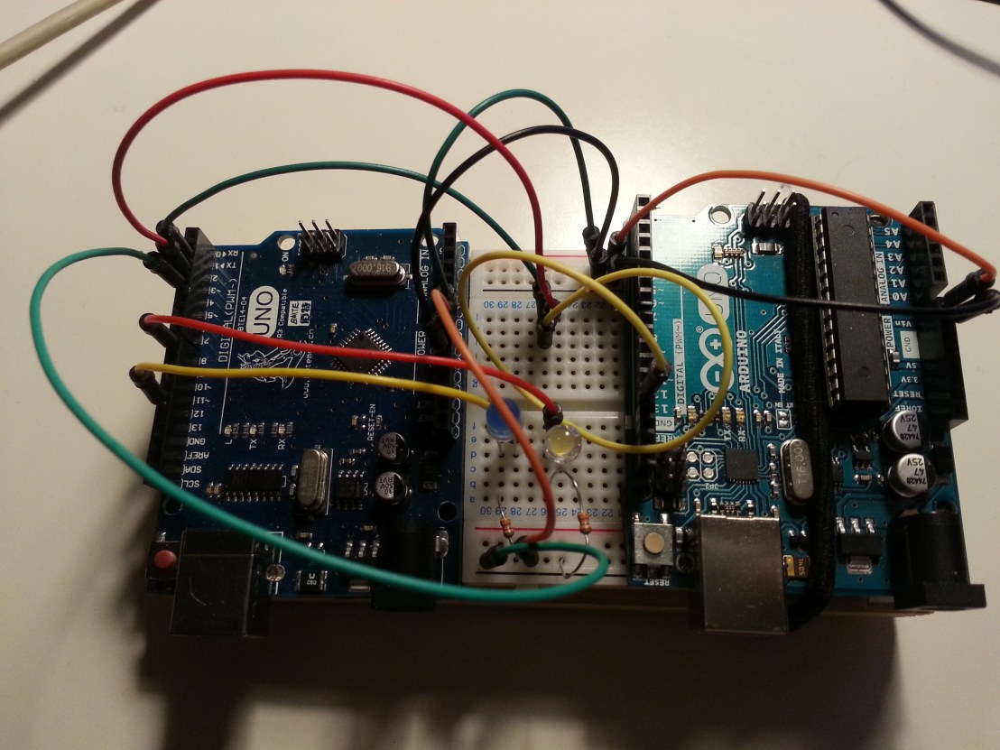
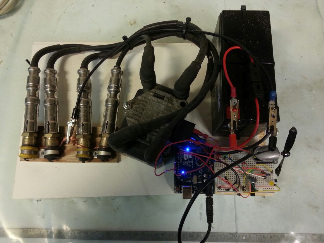
Anyway. With some help from the Arduino Forum, Speeduino forum and Swedish Elektronikforumet. I have noe gotten so far that I have a code that seems to be working and function ok. I had to make my self an engine crank signal simulator. So I took an other Arduino and wrote a simple code to produce an rpm signal to feed the ignition controller. Now I am working on the circuit and I will have to fight the EMP interference from the ignition leads and coil pack. I will mount the electronics in a metal box filled with epoxy. Use sheilded cables and VW automotive coil pach, leads, plugs and harness. This will hopefully be the secondary ignition system on my engine in the future.
Here is a short video of what I have accomplished so far: EIS video
The old magneto ignition is sooo booring…
I have also used an little model engine to simulate the crank signal. But with my Arduino rpm simulator I can choose exactly what rpm to simulate.
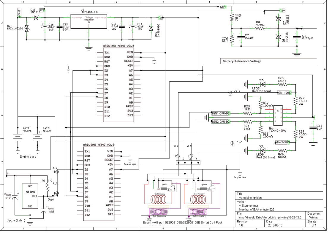
This a draft of the circuit:
Here is the ignition code. (The RPM simulator code is futher down the page) It is always changing, but I think this will work. I will have to do a lot of testing and evaluation with an stroboscope and oscilloscope. After that I will try to run my garden tractor with it.
/****Simple reliable Electronic Ignition System for 4-stroke 4-cylinder wasted spark ignition system.
*****By Anders Stenhammar. 2016, Sweden **********/
// To be able to manipulate the AVR processor timers:
#include <Avr/interrupt.h>
#include <Avr/io.h>
//Pin definitions:
const byte HallPin1 = 2; // Pin nr 2 to Hall sensor
const byte HallPin2 = 3; // Pin nr 3 is also to Hall sensor
const byte IgnOnPin = 4; // Ignition switch
const byte Ign1Pin = 8; // (PORTB,0)
const byte Ign2Pin = 12; // (PORTB,4)
volatile unsigned int cranktime; // Time from 3 degrees to where the coil should start to load.
volatile unsigned int crankingDwellTime; // The time the coil should charge during cranking
volatile long int microseconds; // The microsecondcounter value.
volatile long int half_revolution_time; // The time it takes for the crank to turn 1/2 revolution.
volatile int runningDwellTime; // The time the coil should charge during running
volatile int dwellTime; // The time the coil should charge.
volatile int IgnSystem; // Statusword for active ign system.
volatile byte IgnOn;
/***********************************************************************/
void setup() {
pinMode(Ign1Pin, OUTPUT); // Initialize the Ignition 1 pin as an output.
pinMode(Ign2Pin, OUTPUT); // -“-
pinMode(HallPin1, INPUT_PULLUP); // To get rid of RFI interference
pinMode(HallPin2, INPUT_PULLUP); // -“-
pinMode(IgnOnPin, INPUT_PULLUP); // -“-
bitClear(PORTB, 0); //digitalWrite(Ign2Pin, LOW); //Turn the ignition off in case it’s on
bitClear(PORTB, 4); //digitalWrite(Ign1Pin, LOW); // -“-
attachInterrupt(digitalPinToInterrupt(HallPin1), SensorOn, RISING); //Hall sensor DI for Ignition 1
attachInterrupt(digitalPinToInterrupt(HallPin2), SensorOff, FALLING); //-“- 2
crankingDwellTime = 4000; //in uS
runningDwellTime = 3000; //in uS
half_revolution_time = 0;
IgnSystem = 0; // No ignition system is active (cranking mode).
IgnOn=LOW;
IgnOn = digitalRead(IgnOnPin);
/********** Setup timer2*************/
noInterrupts();
TCCR2A = 0; // Turn off Control register for waveform generation
TCCR2B = 0; // Turn off noise cancelling, turn off edge select, waveform gen mode 0,
TCCR2A |= (1 << WGM21); // Turn on CTC mode (so it will start again) automatically
TIMSK2 |= (1 << OCIE2A); // Set interrupt on compare match.
OCR2A = 8; // Prescaler of 64 gives 4uS per tick, 4uS * 8 = 32uS (32uS = 1 degree at ~5100rpm).
TCNT2 = 0; // Reset timer counter to 0
microseconds = 0; // Preset the us counter variable.
interrupts();
}
//========================================================================
/* The interrupt action for magnet 1: The Timer starts to count up 32 uS at a time.
**********************/
void SensorOff () {
if (IgnOn == HIGH){
half_revolution_time = microseconds; // For engine speed measurement
TCNT2 = 0; // Reset the timer count to 0
microseconds = 0; // reset the uS counter variable
TCCR2B |= (1 << CS22); // Load 64 prescaler, and this starts the timer2!
// While cranking (rpm < 300), the coil nr 2 will start to charge at once.
if ((half_revolution_time>100000)||(half_revolution_time==0)) {
IgnSystem = 2;
bitSet(PORTB,4); //digitalWrite(Ign2Pin, HIGH); // (Turn on coil 2 charging immediately.)
dwellTime = crankingDwellTime; //Setting the dwelltime for cranking.
cranktime = 0; //Setting the cranktime to 0 for immediate coil charging.
}
// While running (rpm >= 300), coil nr 2 will be used at next ignition.
if ((half_revolution_time<=100000)&&(half_revolution_time!=0)){
IgnSystem = 1; //start using coil nr1 instead.
dwellTime = runningDwellTime; //setting the dwelltime for running
}
}
}
/*========================================================================
The interrupt action for magnet 2: The Timer starts to count up 32uS at a time.
********************************/
void SensorOn () {
if (IgnOn == HIGH){
half_revolution_time = microseconds; // For engine speed measurement
TCNT2 = 0; // Reset the timer count to 0
microseconds = 0; // reset the uS counter variable
TCCR2B |= (1 << CS22); // Load 64 prescaler, and this starts the timer2!
// While cranking (rpm < 300), the coil nr 1 will start to charge at once.
if ((half_revolution_time>100000)||(half_revolution_time==0)) {
IgnSystem = 1;
bitSet(PORTB,0); //digitalWrite(Ign1Pin, HIGH); // (Turn on coil 1 charging immediately,)
dwellTime = crankingDwellTime; //setting the dwelltime for cranking.
cranktime = 0; //Setting the cranktime to 0 for immediate coil charging.
}
// While running (rpm >= 300), coil nr 2 will be used at next ignition.
if ((half_revolution_time<=100000)&&(half_revolution_time!=0)){
IgnSystem = 2; //start using coil nr2 instead.
dwellTime = runningDwellTime; //setting the dwelltime for running
}
}
}
/*=============================================================================
The Interrupt Service Routine for Timer2 that will be executed each time the timer reach the compare match register (32uS)*/
ISR(TIMER2_COMPA_vect) {
microseconds=microseconds+32; // Increases the variable “microseconds” by 32 every time the ISR is executed).
/************ coil charging*****************************/
if ((microseconds >= cranktime) && (microseconds < (cranktime+dwellTime))) {
if (IgnSystem == 1) { //If ignitionsystem 1 is selected, then:
bitSet(PORTB,0); //(Turn on coil 1 charging.) //digitalWrite(Ign1Pin, HIGH);
} if (IgnSystem == 2) { //If ignitionsystem 2 is selected, then:
bitSet(PORTB,4); //(Turn on coil 2 charging.) //digitalWrite(Ign2Pin, HIGH);
}
}
/***********Discharge coilspark*******************************************/
// When the microseconds has reached the cranktime and dwelltime, then:
if (microseconds >=(cranktime + dwellTime)) {
bitClear(PORTB, 0); //digitalWrite(Ign1Pin, LOW); //( Stop charging coil 1. (Gives spark))
bitClear(PORTB, 4); // digitalWrite(Ign2Pin, LOW); // As above.
// _________________________________________________________________________________________________________
if (microseconds > 100000) { // If the engine has stopped or still cranking, stop and reset the timer.
TCCR2B &= ~(1 << CS22); // Clear the prescaler, and this stops the timer2!
TCCR2B = 0;
microseconds = 0;
}
}
}
/***********************************************************/
void loop() {
IgnOn = digitalRead(IgnOnPin); // Check the status of the ignition switch
// Ignition advance curve.
//Following numbers are based on a excell sheet with the advance curve attached.
if (half_revolution_time> 6208 ){ ///Advance 0 @ >4100 rpm (rev limitation)
cranktime=7195-dwellTime;}
if ((half_revolution_time<= 7500 ) && (half_revolution_time> 7317 )){ ///Advance 28 @ 4000-4100 rpm (rev limitation)
cranktime=6208-dwellTime;}
if ((half_revolution_time<= 9091 ) && (half_revolution_time> 7500 )){ ///Advance 28 @ 4000-3300 rpm
cranktime=7525-dwellTime;}
if ((half_revolution_time<= 10000 ) && (half_revolution_time> 9091 )){ ///Advance 27,5 @ 3300-3000 rpm
cranktime=8306-dwellTime;}
if ((half_revolution_time<= 10714 ) && (half_revolution_time> 10000 )){ ///Advance 27 @ 3000-2800 rpm
cranktime=8929-dwellTime;}
if ((half_revolution_time<= 11111 ) && (half_revolution_time> 10714 )){ ///Advance 26 @ 2800-2700 rpm
cranktime=9321-dwellTime;}
if ((half_revolution_time<= 12500 ) && (half_revolution_time> 11111 )){ ///Advance 24 @ 2700-2400 rpm
cranktime=10625-dwellTime;}
if ((half_revolution_time<= 15000 ) && (half_revolution_time> 12500 )){ ///Advance 22 @ 2400-2000 rpm
cranktime=12917-dwellTime;}
if ((half_revolution_time<= 15789 ) && (half_revolution_time> 15000 )){ ///Advance 20 @ 2000-1900 rpm
cranktime=13772-dwellTime;}
if ((half_revolution_time<= 16667 ) && (half_revolution_time> 15789 )){ ///Advance 18 1900-1800 rpm
cranktime=14722-dwellTime;}
if ((half_revolution_time<= 18750 ) && (half_revolution_time>= 16667 )){ //Advance 16 @ 1800-1600 rpm
cranktime=16771-dwellTime;}
if ((half_revolution_time<= 20000 ) && (half_revolution_time>= 18750 )){ //Advance 14 @ 1600-1500 rpm
cranktime=18111-dwellTime;}
if ((half_revolution_time<= 21429 ) && (half_revolution_time>=20000 )){ //Advance 12 @ 1500-1400 rpm
cranktime=19643-dwellTime;}
if ((half_revolution_time<=25000 ) && (half_revolution_time>= 21429 )){ //Advance 10 @ 1400-1200 rpm
cranktime=23194-dwellTime;}
if ((half_revolution_time<=27273 ) && (half_revolution_time>=25000 )){ //Advance 9 @ 1200-1100 rpm
cranktime=25455-dwellTime;}
if ((half_revolution_time<= 30000) && (half_revolution_time>=27273 )){ //Advance 8 @ 1100-1000 rpm
cranktime=28167-dwellTime;}
if ((half_revolution_time<= 33333) && (half_revolution_time>= 30000 )){ //Advance 7,5 @ 1000-900 rpm
cranktime=31389-dwellTime;}
if ((half_revolution_time<=42857 ) && (half_revolution_time>= 33333 )){ //Advance 7 @ 900-700 rpm
cranktime=40476-dwellTime;}
if ((half_revolution_time<=50000 ) && (half_revolution_time>= 42857)){ //Advance 7 @ 700-600 rpm
cranktime=47222-dwellTime;}
if ((half_revolution_time<= 75000 ) && (half_revolution_time>= 50000 )){ //Advance 9 @ 600-400 rpm
cranktime=70000-dwellTime;}
if ((half_revolution_time<= 85714) && (half_revolution_time>= 75000 )){ //Advance 2 @ 400-350 rpm
cranktime=83333-dwellTime;}
if ((half_revolution_time<= 100000 ) && (half_revolution_time>= 85714 )){ //Advance -2,5 @ 350-300 rpm
cranktime=99722-dwellTime;}
}
// Thank you for helping me improve this code. Please send feedback to anders.stenhammar84@gmail.com
Here is the rpm code:
/*The circuit:
* Potentiometer attached to analog input 0
* center pin of the potentiometer to the analog pin
* one side pin (either one) to ground
* the other side pin to +5V
* LED anode (long leg) attached to digital output 13
* LED cathode (short leg) attached to ground
*/
// To be able to manipulate the AVR processor timers:
#include <Avr/interrupt.h>
#include <Avr/io.h>
const int HallPin1 = 13; // Hall latch sensor output (PORTB,0)
const int HallPin2 = 12; // Hall latch sensor output (PORTB,0)
int TrimPotPin = A0; // select the input pin for the potentiometer
int sensorValue = 0; // variable to store the value coming from the sensor
unsigned int rpm;
long int timeold;
volatile long int microseconds; // The microsecondcounter value.
volatile long int half_revolution_time; // The time it takes for the crank to turn 1/2 revolution (The value of Trimpot.
volatile long half_revolutionStart;
volatile int half_revolutions; // Hall sensor trigger counter
void setup() {
Serial.begin(9600);
pinMode(HallPin1, OUTPUT);
digitalWrite(HallPin1, LOW);
half_revolution_time=0;
microseconds = 0; // Preset the us counter variable.
/********** Setup timer2*************/
noInterrupts();
TCCR2A = 0; // Turn off Control register for waveform generation
TCCR2B = 0; // Turn off noise cancelling, turn off edge select, waveform gen mode 0,
TCCR2A |= (1 << WGM21); // Turn on CTC mode (so it will start again) automatically
TIMSK2 |= (1 << OCIE2A); // Set interrupt on compare match.
OCR2A = 8; // Prescaler of 64 gives 4uS per tick, 4uS * 8 = 32uS (32uS = 1 degree at ~5100rpm).
TCNT2 = 0; // Reset timer counter to 0
TCCR2B |= (1 << CS22); // Load 64 prescaler, and this starts the timer2!
interrupts();
}
//The Interrupt Service Routine for Timer2 that will be executed each time the timer reach the compare match register (32uS)*/
//______________________________________________________________________________________________________________________________
ISR(TIMER2_COMPA_vect) {
microseconds=microseconds+32; // Increases the variable “microseconds” by 32 every time the ISR is executed).
if (microseconds >= half_revolution_time){
if (digitalRead (HallPin1)==LOW){
digitalWrite(HallPin1, HIGH); // North magnet is approaching the Hall sensor
half_revolutions++;
}else{
digitalWrite(HallPin1, LOW); // South magnet is approaching the Hall sensor
half_revolutions++;
}
microseconds = 0; // Reset the us counter variable.
TCNT2 = 0; // Reset timer counter to 0
if (half_revolutions >= 80) {
// read the value from the sensor:
sensorValue = analogRead(TrimPotPin);
// map it to the range of the analog out:
half_revolution_time = map(sensorValue, 0, 1024, 0, 160000);
//RPM measurement
rpm =60*1000000/half_revolution_time/2;
half_revolutions = 0;
Serial.print(” half_revolution_time “);
Serial.println(half_revolution_time);
Serial.print(” rpm “);
Serial.println(rpm);
}
}
}
void loop() {
// if(rpm>4200){
// rpm=4200;
// half_revolution_time=7320;}
// if(rpm<10){
// rpm=10;}
// // print the results to the serial monitor:
// Serial.print(“sensor = ” );
// Serial.print(sensorValue);
//}
//half_revolution_time=50000;
// if ((half_revolution_time>7000)&&(half_revolution_time<30000000)){ //Engine is running
// TCCR2B |= (1 << CS22); // Load 64 prescaler, and this starts the timer2!
// }
// if (half_revolution_time>=30000000){ // Engine is standing still
// TCCR2B &= ~(1 << CS22); // Clear the prescaler, and this stops the timer2!
//}
//wait 2 milliseconds before the next loop
// for the analog-to-digital converter to settle
// after the last reading:
//delay(2);
}


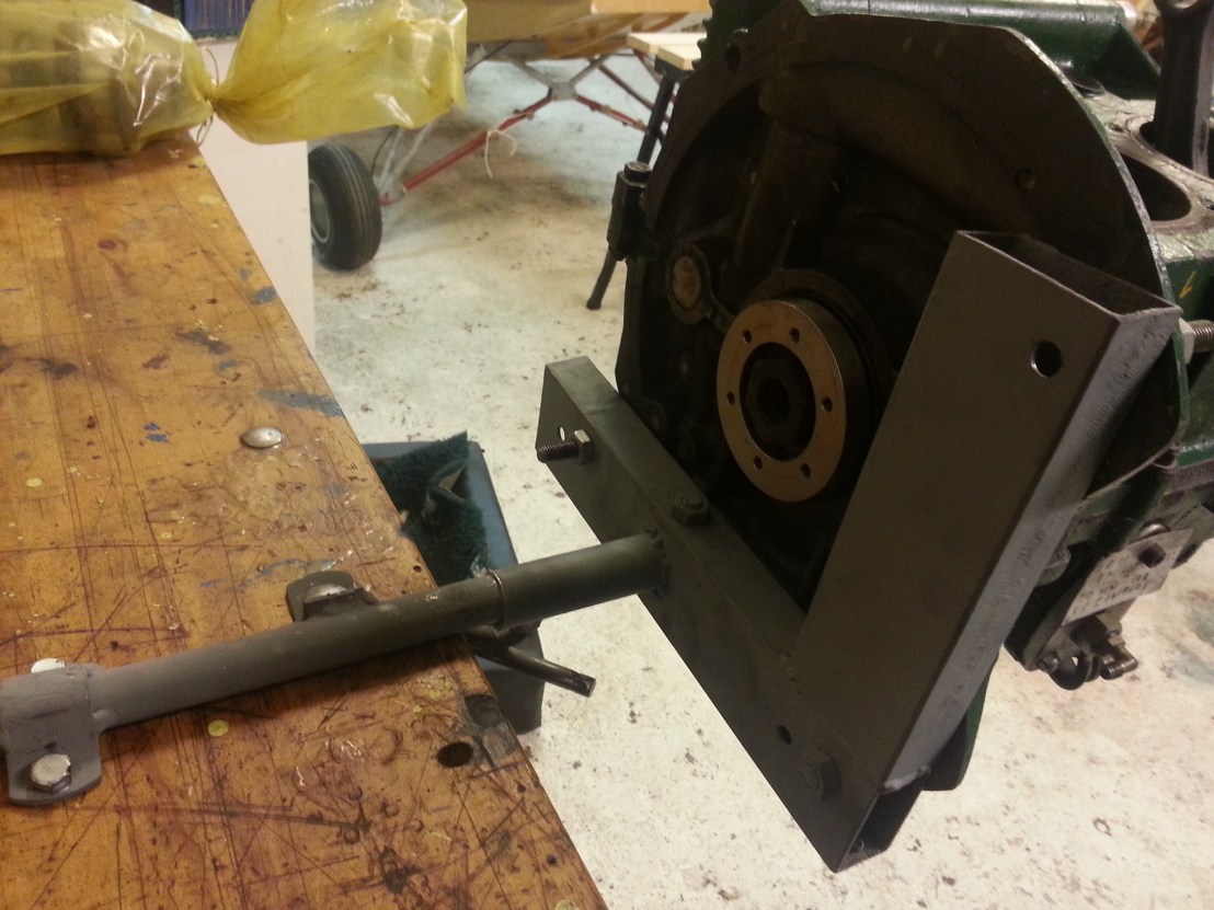
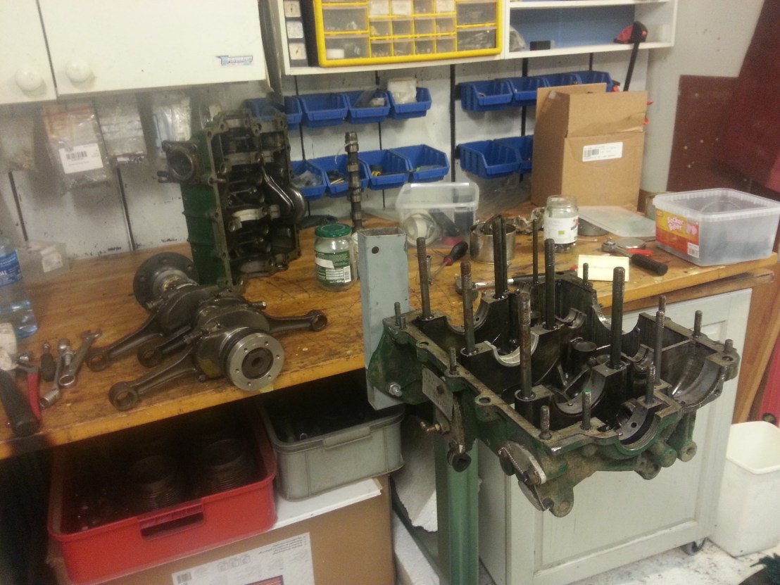
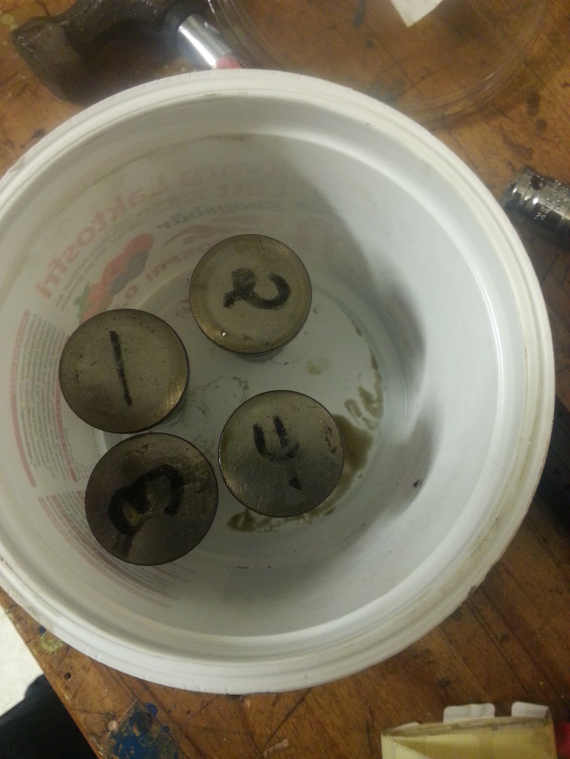
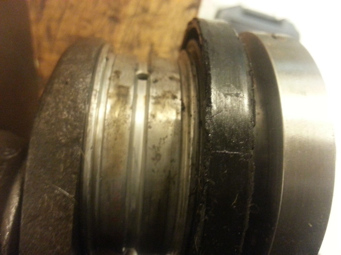
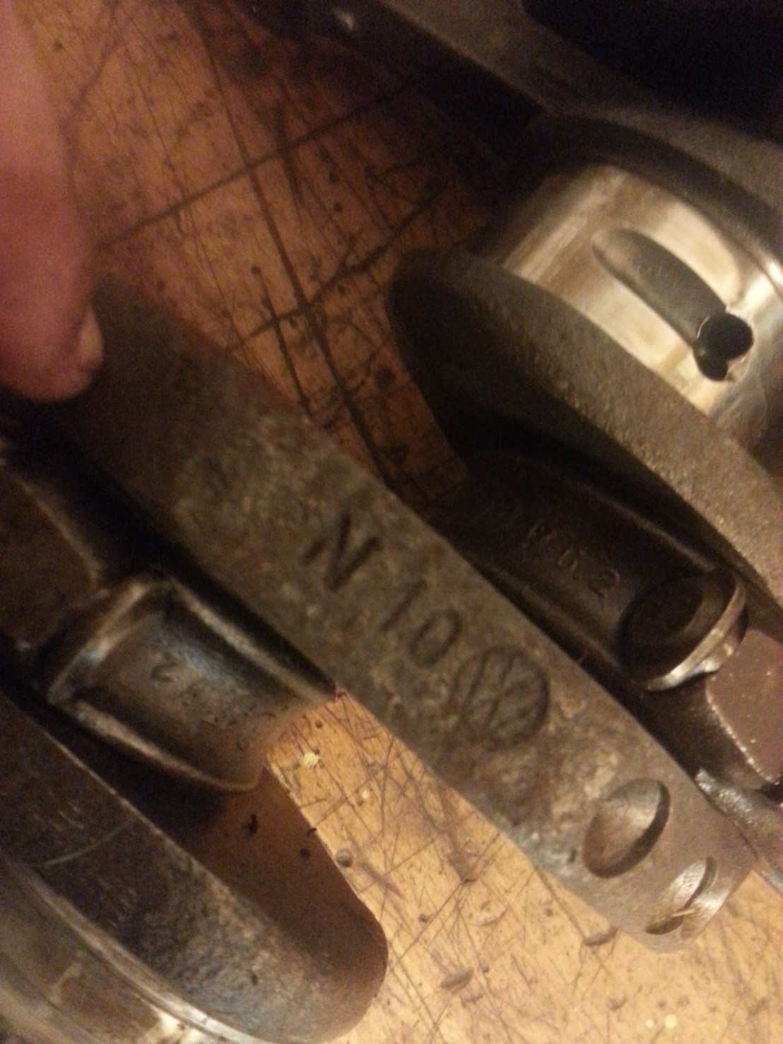
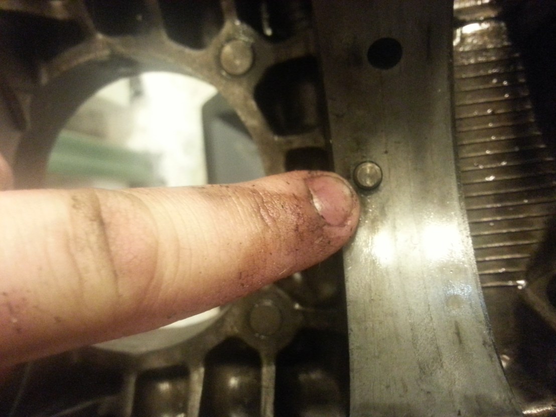
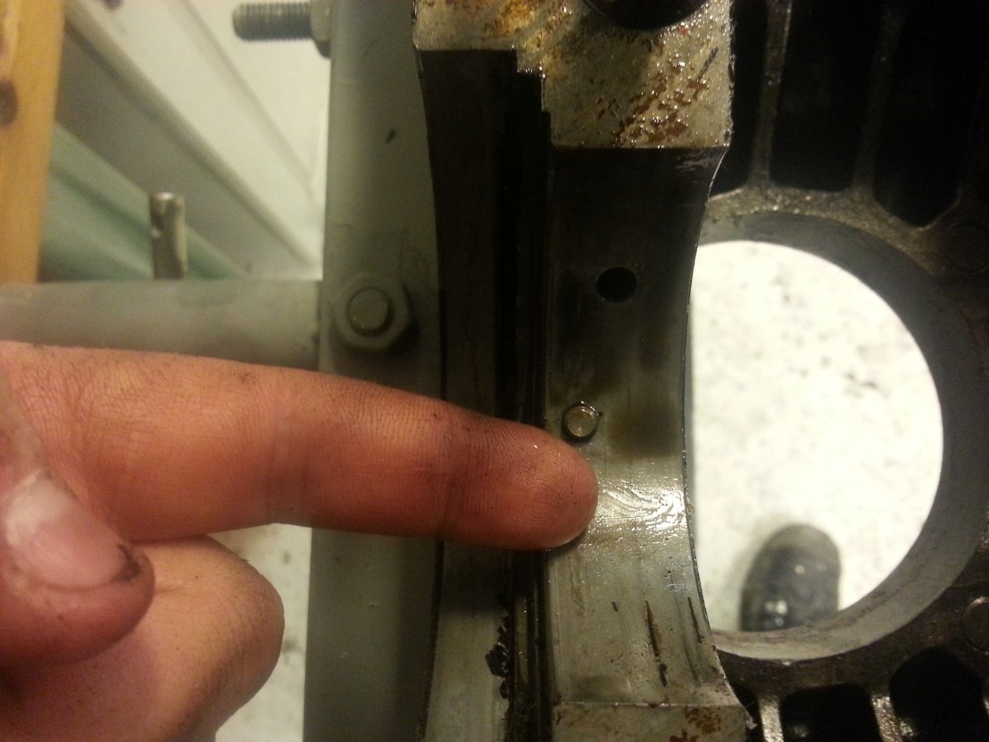
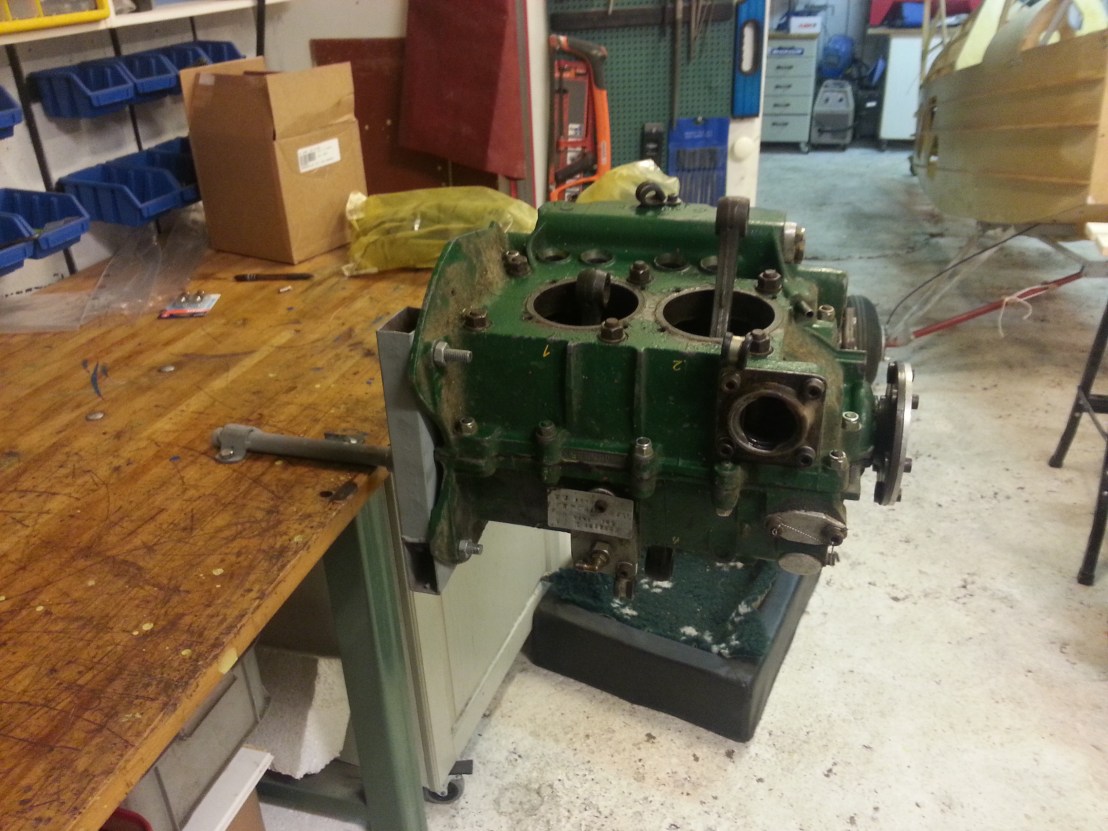 Today I started tearing down the engine I bought. It has only 150 flying hours but it has not been touched sinse 1986. Still there was no corrosion or rust at all. The owner has had the engine conserved and stored in a dry place all the time. It is an Danish 1600cc aeroconversion engine. So what I will do is to take it all apart, send the crankshaft to magnaflux inspection, have all the parts measured and ballanced, hace the case modified to fit 1834cc barrels and build it as an 1834cc engine.