Its time to make a special page for this project. I will post the latest info about the project on this page. I will dedicate the system for aircraft use, but of course you can use it on a car, like for an example the VW Beetle.
Here is the Open source Aeroduino Project files!
https://create.arduino.cc/editor/AndersStenhammar/94756ac2-1296-4ad6-b347-508de26cc50a/preview?embed” target=”_blank”>And here is the crank signal simulator
Remember that this is an unfinished live ongoing project!
System description
Easy starting, even with hand propping
When starting, the spark plug fires at 3 degrees AFTER TDC. This makes kick-back impossible. Additionally, the spark energy is boosted.

When the first few revolutions have been completed the advance is mapped to the curve above. This results in a very positive but gentle start.
The spark energy is produced regardless of the speed at which the prop is pulled through TDC. You need only to pull the prop through TDC cleanly, not quickly.
No adjustments, no moving parts
It is a fit and forget system. There is nothing to wear. No adjustment is required or possible. It is tolerant of dirt. Maintenance consists of checking that the wiring connections and mountings are in good order. The battery capacity should be checked occasionally.
Low power requirement
As it is energy efficient, each system requires only a maximum of 350 mA at 12V at 3,000 RPM.
Compact and light
As can be seen from the pictures and drawings. One controller weighs 100g, and one coil weighs 900g
VAG (Bosch) coilpack are used as they are well tried, readily available and reasonably priced. Being vacuum impregnated with epoxy and having sealed EHT connector, they are very robust and water proof. They have a built in ignitor mounted on top. Individual ignition leads are available from accessory dealers.
Each ignition controller drives one coilpack and one coilpack drives 4 plugs. No distributor is required. In order to be able to set the time for the next spark to occur, the ignition controller needs to know when the crankshaft passes the reference points. It gets this with the aid of a magnetic sensor and two magnets 180 degrees apart that are fixed to a rotor on the crankshaft. One has the N pole facing out, the other has the S-pole facing out. The N-pole corresponds to 3 degrees After Top Dead Center for cylinders 1 and 3 (rear) and the S-pole corresponds to 3 deg. ATDC for cylinders 2 and 4 (front). Ths system will easily be modified to be able to run on 2 cylinder engines.
When the engine is running, the crankshaft rotates and the magnetic sensor produces two reference segnals each revolution. These are fed to a microcontroller, which records the time of each segnals to microseconds accuracy on an internal clock. From these times the RPM is calculated and the required timing advance angle is derived. The actual time of the next spark is calculated, and when the clock reaches this value, the appropriate pair of plugs fire. Which pair is fired depends on whether the last reference pulse was from a N-pole or a S-pole. Using a Latching (bistable) Hall sensor makes this possible.
For starting, the priority is to prevent kickback and ensure a big spark. To achieve this the spark occurs at 3 degrees AFTER TDC. The active edge of each magnet is physically installed at this point and this generates the spark immediately after dwell time (coil charging time).
A spark occurs every time a piston approaches TDC. Thus one spark is “wasted” as it occurs at the end of the exhaust phase, and so has no effect. The benefit of this is that no distributor is required and the accuracy of the spark timing is improved, as the timing is taken directly from the crank, not through the gear driven camshaft.
Tips and settings
Set plug gaps to 0.9 to 1.0 mm .
Do not use batteries smaller than 7Ah for the main or 2.8 Ah for the backup.
KEEP IT COOL
The main enemy of reliability of electrical and electronic systems is heat. To avoid problems keep the temperature of the coils below 50 C when the engine is running ie when air is being blown through the engine compartment. This may mean that special provision has to be made to direct fresh air at them. Compared to the cooling requirements of the engine, only a tiny amount is required. The Aeroduino controller is recommended be mounted behind the firewall inside the cabin.
Timing sensor
The external sensor is connected to the controller with a shielded lead which has a connector at its other end. This plugs into the Aeroduino controller. The external sensor is mounted within a 12.7 dia X 38 long (½” dia X 1 ½”long) AL tube. It can be fixed to the front of the VW crankcase with a suitable mount on the existing M6 tapped hole.
Coil pack
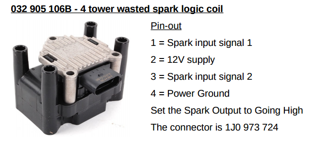
Firing order: 1-3-4-2
4 cylinder wasted-spark ignition coil with built in 2 channel ignition amplifier (ignitor) for use directly with Adaptronic or other ECU’s that output a low corrent positive trigger. These coils produce a very healthy spark, much stronger than the average 4 cylinder Zetec coil, etc. This is in part thanks to the in built ignitors removing the losses you might normally have in the low tension circuit of a normal ‘dumb’ coil.
The 4 pin plug for this coil pack is available seperately if you require it. They accept the common M4 (4mm pin inside turret) type HT leads.
The resistance of the spark plug wires, should be 4000-6000 Ohms.
Coil pack mounting requires that the unit is earthed, ideally bolted to the engine block or body earth at least. With this coil pack there are 3 mounting holes, they should be earthed by using bolts that screw directly into a plate or mounting that is earthed.
The unit also has an in-built safety timer to protect itself in the event of a perminant live (or inverted ignition output) being present on one or both of the inputs.
HT leads are marked A,B,C & D on the coil which represent cylinders 1,2,3 & 4
Timing curve.
The timing is calculated using a math formula based on simple math functions. Just straight lines between points in a diagram. No derivata och fancy. You could also use a lot if IF functions without any math.
You can view and edit a copy of the latest excell file here. Remember to save it on your computer before editing.

Arduino code
The code is always under development. I am no expert at writing code, so I stick to the simple stuff. Using the Arduino language as much as possible. I have used some direct port writing to speed stuff up some, but the code needs to be simple to be safe.
